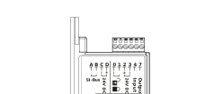
Analogue connection for smoke protection and fire-rated doors
Wiring diagram with emergency power buffer | |
|---|---|
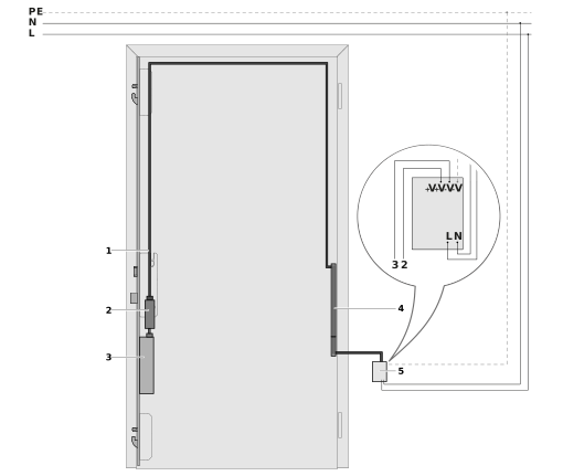 | |
1 | Fire-resistant cable type =K-FS, length 12 m (6-pole) |
2 | Emergency power buffer variant A1 |
3 | Multi-point lock with electromechanical drive GEP |
4 | Cable transfer for installation in fire-rated doors |
5 | Top-hat rail power supply |
1 | Fire-resistant cable type =K-FS, length 12 m (6-pole) |
2 | Emergency power buffer variant A0 |
3 | Multi-point lock with electromechanical drive GENIUS |
4 | Cable transfer for installation in fire-rated doors |
5 | Top-hat rail power supply |
Wiring diagram | |
|---|---|
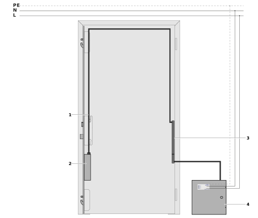 | |
1 | Fire-resistant cable type =K-FS, length 12 m (6-pole) |
2 | Multi-point lock with electromechanical drive GENIUS |
3 | Cable transfer for installation in fire-rated doors |
4 | Uninterruptible power supply |
1 | Fire-resistant cable type =K-FS, length 12 m (6-pole) |
2 | Multi-point lock with electromechanical drive GEP |
3 | Cable transfer for installation in fire-rated doors |
4 | Uninterruptible power supply |
Power supply with USV | |
|---|---|
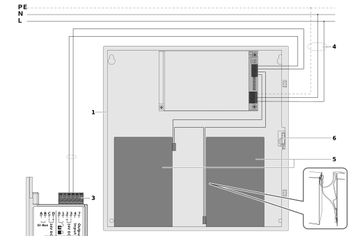 | |
1 | Uninterruptible power supply |
2 | 2-wire cable for power supply to drive |
3 | Electromechanical GENIUS drive |
4 | 3-wire cable with protective conductor |
5 | Rechargeable battery for uninterrupted power supply |
6 | Micro switch for detection of opened casing |
1 | Uninterruptible power supply |
2 | 2-wire cable for power supply to drive |
3 | Electromechanical drive GEP |
4 | 3-wire cable with protective conductor |
5 | Rechargeable battery for uninterrupted power supply |
6 | Micro switch for detection of opened casing |